Prerequisites: CCNP level skills.
Quick Note:
I must keep my Video Notes as short as possible since Youtube upload takes a moment. Each post is going to have only two videos: the answer to the question, and the lab solution.
Cisco IOS OSPF modes of Operation:
- Point-to-point (Cisco)
- Broadcast (Cisco)
- Non-broadcast (RFC 2328)
- Point-to-multipoint (RFC 2328)
- Point-to-multipoint non-broadcast (Cisco)
Again, the tasks helping me understand the OSPF operation are going to be structured in a similar way to my previous post (OSPF in point-to-point networks)
Topology
Pic. 1 - OSPF Broadcast Network.

Workflow
- Get familiar with the topology. Pay attention to what Router IDs are on each router.
- Read the 'Task List'.
- Read the 'Questions' and provide the answers BEFORE configuring the routers.
- Configure the lab as per 'Task List' .
- Compare the answers (step 3) with the lab results.
- Configure IP adresses as per topology diagram (pic. 1). Check the layer 3 connectivity.
- Enable OSPF routing protocol. All interfaces should be in area 0.
- R1 should be elected the DR and R2 should be elected the BDR on the broadcast segment.
- Make sure that loopback interfaces are advertised with their configured network mask (/24).
- On each router use different method of enabling OSPF on the interfaces.
- What is the default OSPF mode of operation on broadcast links?
- What are the default timers (hello/dead) used on broadcast links?
- What is the role of DR/BDR on broadcast/NBMA segment (more detailed answer can be found in my other blog here)?
- If all routers participate in the election of DR/BDR what parameter(s) determines these roles?
- If the DR/BDR have been elected, what is going to happen if the router with the highest router ID joins the broadcast/NBMA network?
- What is going to happen if DR is no longer available and BDR has lower priority than the newly introduced router?
- What is the implication of using the priority with the value of 0?
- If R1 is the DR and R2 is the BDR, what is going to be OSPF state between R3 and R4 in the topology used (pic.1)?
- What is the address used to advertise updates on broadcast segment?
Lab Solution
Note!
Since the lab stipulates that R1 must be the DR and R2 the BDR, the order of operation does matter (unless I want to clear the ip ospf process later which is a waste of time). That's why I start my configuration with R1 and R2 first by changing the priority on F1/0 interfaces.
Note!
Because the loopback interfaces area advertised as stub network (/32) by default, I change the mode of operation to point-to-point so OSPF advertises them with their native (configured /24) network mask.
Note!
I am going to use different ways of enabling OSPF on the interfaces. In practice (especially in the CCIE lab), the most specific wildcard mask is recommended unless specified otherwise.
R1 Configuration:
!
interface Loopback0
ip address 172.16.101.1 255.255.255.0
ip ospf network point-to-point
ip ospf 1 area 0
!
interface FastEthernet1/0
ip address 10.1.1.1 255.255.255.0
ip ospf priority 20
ip ospf 1 area 0
!
ip address 10.1.1.1 255.255.255.0
ip ospf priority 20
ip ospf 1 area 0
!
interface FastEthernet1/0
ip address 10.1.1.1 255.255.255.0
ip ospf priority 20
ip ospf 1 area 0
!
ip address 10.1.1.1 255.255.255.0
ip ospf priority 20
ip ospf 1 area 0
!
R2 Configuration:
!
interface Loopback0
ip address 172.16.102.2 255.255.255.0
ip ospf network point-to-point
!
ip ospf network point-to-point
!
interface FastEthernet1/0
ip address 10.1.1.2 255.255.255.0
ip ospf priority 10
!
ip address 10.1.1.2 255.255.255.0
ip ospf priority 10
!
router ospf 1
router-id 2.2.2.2
log-adjacency-changes
network 10.1.1.2 0.0.0.0 area 0
network 172.16.102.2 0.0.0.0 area 0
!
router-id 2.2.2.2
log-adjacency-changes
network 10.1.1.2 0.0.0.0 area 0
network 172.16.102.2 0.0.0.0 area 0
!
R3 Configuration:
!
interface Loopback0
ip address 172.16.103.3 255.255.255.0
ip ospf network point-to-point
!
ip ospf network point-to-point
!
interface FastEthernet1/0
ip address 10.1.1.3 255.255.255.0
!
ip address 10.1.1.3 255.255.255.0
!
router ospf 1
router-id 3.3.3.3
log-adjacency-changes
network 0.0.0.0 255.255.255.255 area 0
!
router-id 3.3.3.3
log-adjacency-changes
network 0.0.0.0 255.255.255.255 area 0
!
R4 Configuration:
!
interface Loopback0
ip address 172.16.104.4 255.255.255.0
ip ospf network point-to-point
!
ip ospf network point-to-point
!
interface FastEthernet1/0
ip address 10.1.1.4 255.255.255.0
!
ip address 10.1.1.4 255.255.255.0
!
router ospf 1
router-id 4.4.4.4
log-adjacency-changes
redistribute connected subnets
network 10.1.1.0 0.0.0.255 area 0
!
router-id 4.4.4.4
log-adjacency-changes
redistribute connected subnets
network 10.1.1.0 0.0.0.255 area 0
!
Verification
Note!
On R4 OSPF neighbor adjacencies. Pay attention, R4 has 2-way (correct) state with R3. Full adjacency established between R1 (DR) and R2 (BDR).
Pic. 2 - OSPF Adjacencies

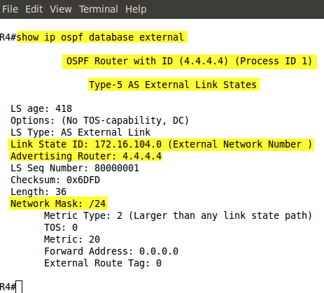
In my configuration R4 redistributes connected network (Lo0) into OSPF. This shows as E2 (external type 2) by default.
Pic. 3
R4 learns all subnets (loopbacks advertised by R1, R2, and R3) with /24 network mask. This is the result of using point-to-point mode of operation configured on the loopback interfaces.
Pic. 4 - OSPF Routing Table.

Note!
R1 (also R2 and R4) learns 172.16.104.0/24 as external (redistributed) subnet.
Pic. 5 - OSPF External Subnet.
